@seb.apprenti
Yeah, that should work. You might need to write your vehicle order (VO) to it with NCSExpert so it knows to use the correct DTC limits and characteristic curve.
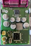
The key is the connector color. We need the EKPM2 or EKPM3 with the maroon connectors. The white connectors are for brushless fuel pumps. I also see EKP modules with green connectors on Ebay. They appear to be for M vehicles. Not sure of the technical differences, only going off the item listings.
From: https://www.newtis.info/tisv2/a/en/...y/low-pressure-fuel-system-components/XhflKCR
Yeah, that should work. You might need to write your vehicle order (VO) to it with NCSExpert so it knows to use the correct DTC limits and characteristic curve.
The key is the connector color. We need the EKPM2 or EKPM3 with the maroon connectors. The white connectors are for brushless fuel pumps. I also see EKP modules with green connectors on Ebay. They appear to be for M vehicles. Not sure of the technical differences, only going off the item listings.
Control unit variants
Various electric fuel pumps can be operated with the electronic fuel pump control module (EKPS). To do so, there are the following 2 control unit variants:
With the direct current version, the electric fuel pump is driven by a direct current motor with permanent magnet. With the rotary current version, the electric fuel pump is driven by a brushless three-phase motor with permanent magnet. With the corresponding encoding, it is possible to operate various electric fuel pumps with the relevant variant of the control unit. The two control unit versions are distinguished visually by the colour of their connectors: The direct current variant has a maroon connector, the rotary current version has a white connector.
- Direct current (DC) version
- Rotary current (AC) version
From: https://www.newtis.info/tisv2/a/en/...y/low-pressure-fuel-system-components/XhflKCR