DIY DIY EKPM3 Active Cooling for LPFP

ajm8127

Specialist
Jul 16, 2020
69
135
0
PA - US
Ride
2007 E90 335i
So I am still gronking the write-up and the spreadsheet. I made a variety of changes to the spreadsheet (which I hope are correct) and help clarify the compare/contrast on the data.

So here are my questions:
  • Why did BMW move to the EKPM3? Are there benefits to which we are unaware, in the above analysis?
  • Is the EKPM2, actually, best suited to pursue? (you mention decreasing rise/fall times ala programming?)
  • Might there be some dialog on the desirable performance behaviors and plus/minus? (not to be in minutiae ... but enough to understand what/why we care about some things. Heat is obvious, other things less obvious to me).
I'll stop there :). I'll also note that I'm planning to move to the Walbro 535LPH F90000295, which @martymil has been vetting out successfully. If you have not seen this, @ajm8127 , you may find it interesting: https://www.spoolstreet.com/threads/ti-automotive-walbro-274-vs-285-vs-295.5882/post-95536

Filippo

I see a typo in the Google Docs spreadsheet, but it is my fault. The frequency is in kilohertz, not hertz. Also I didn't really use a Walbro 450, but simulated the current draw of one. Might not be worth the distinction, I'll let you decide. Otherwise it looks fine.

  • I believe BMW built (had Helbako build) the EKPM3 because it has less components and complexity than the EKPM2. At the time the M2 was built, the half bridge switches on the market were probably not capable of handing the current needed by the fuel pump, so they were forced to use a MOSFET and driver. The EKPM3 reduces part count, moves to all surface mount and gains lead-free status in HW 06. Their hand could also have been forced by part obsolescence or it could have just made sense based on the economics or ability to gain lead-free status.
  • I do believe the hardware on the EKPM2 is "better" than the EKPM3 in that is wastes less power and therefore it will not get as hot as the EKPM3.
  • It's all about heat and wasted energy. The lower resistances and slower switching speed of the EKPM2 makes it the better candidate to drive a high power pump. The MOSFET is rated all the way up to 75 amps, package limited. I have seen the EKPM2 switch at least 2.5 times faster than the EKPM3 best case (BTN8982 with 0 ohms pin 5 to GND). We can modify the EKPM3, but the next step is to change the inductor to a lower DCR one, like the EKPM2 has, so why not just pursue the stock hardware EKPM2 instead of modifying an EKPM3 to reduce it's power dissipation close to that of the EKPM2.
I will check out the other thread.
 

NoQuarter

Major
Nov 24, 2017
1,662
1,066
0
Indiana, USA
Ride
Z4 35is, 535xi, X5 35i
Great explanation.

For this device, it is switching between 2 different mosfets right? What is purpose of that?
 

ajm8127

Specialist
Jul 16, 2020
69
135
0
PA - US
Ride
2007 E90 335i
Great explanation.

For this device, it is switching between 2 different mosfets right? What is purpose of that?

Only one MOSFET is needed to control the power from the battery. It is known as a high side switch, because it is between the power supply (high potential) and the load. A low side switch is between the load and ground (low potential). A high side and low side switch together is know as half of a "H bridge". The BTN7960 and BTN8982 are both half of an H bridge. An full H bridge is used when you want to control the direction and speed of a motor. It can connect either terminal of a DC motor to the positive supply or ground to change the polarity and direction of rotation of the motor which isn't needed in this application.

When you are switching an inductive load like a motor, every time the motor turns off there is a voltage spike. This voltage spike needs a path back to the other motor terminal so it can dissipate safely. A "flyback diode" takes care of this.

On the EKPM2 there is a single high side MOSFET and a flyback diode. On the EKPM3 a half H bridge is used so the high side switch supplies power to the motor winding and the low side switch is turned on as soon as the high side is turned off and this allows the voltage spike to dissipate safely. The EKPM3 needs no external diode because the low side switch provides that function.
 

ajm8127

Specialist
Jul 16, 2020
69
135
0
PA - US
Ride
2007 E90 335i
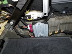
I wanted to share the passive cooling modifications on my EKPM2. This should work for the EKPM3 as well. I have an 2007 E90, so if your chassis is different your EKP might mount in a different location and you might need a different solution. In the case of Filippo's E89 it looks like the EKP mounts directly to the chassis instead of a separate bracket. In this case maybe just changing the pad internally and adding one between the EKP and chassis would be a solution. In the E90 the EKP is mounted to a separate bracket that is not all that large and is not effective at conducting the heat to the chassis. See below

E90 EKP Mounting:
1597764965234.png


I bought a new gap pad and heat sink from Digikey:


I installed the new gap pad in place of the old pad. I couldn't find a single piece big enough at this thermal conductivity, so I used two pieces next to each other. Don't over tighten the PCB mounting screws. It would probably be a good idea to use lock tight and get then snug, but not so tight the gap pad material is squeezed out. It is fairly soft. You can make out the ends of the heat sink mounting screws in the picture - there are two. Make sure they are not long enough to touch the board and cause a short.

NOTE: IT IS IMPERATIVE THAT THE PAD USED ON THE INSIDE OF THE EKP BE NON-CONDUCTIVE. GRAPHITE IS A NEW MATERIAL BEING USED AS A THERMAL INTERFACE BUT IT CONDUCTS ELECTRICITY. DO NOT USE A CONDUCTIVE PAD INSIDE THE EKP! CHOSE A SILICONE BASED PAD INSTEAD.

20200725_113841_HDR.jpg


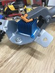
I trimmed the original mounting ears from the heat sink so when I cut a hole in the EKP mounting plate (not pictured) there was still enough material to keep it rigid. I removed part of the outside fins to make new holes. I tapped the back plate of the EKP. It is thin in some spots so be careful tapping and tightening the screws. I cut a hole in my mounting plate to accommodate the heat sink. You can't see it, but I put thermal paste between the EKP back plate and the heat sink.

20200725_113858_HDR.jpg


With the EKP mounted I noticed the heat sink was close to a bundle of wires. I covered that bundle with spiral wrap to prevent wearing a hole in the wire insulation. It doesn't touch the heat sink, but with vibration I just wanted to be sure. The heat sink should be oriented so the fins are vertical. This will allow convection to pull heat away from the heat sink.

20200725_171704.jpg


Unfortunately I don't have any before and after data, but I don't think it is unreasonable to say changing the thermal pad and adding the heatsink is a step in the right direction. The parts are cheap and it didn't that all that long to do this.

Let me know what you think.

[EDIT]

I want to add that it is not necessary to mount the heat sink directly to the module base plate as I have done, it could also be mounted to the bottom of the mounting bracket as well. That way you don't need to cut a hole in the bracket. If you go this route you need additional gap pads between the module and the bracket (the entire surface if possible) and be sure to put some thermal interface material (gap pad, thermal paste) between the bracket and the heat sink. Thermal epoxy might be best because if you screw the heat sink to the bracket, those screws could interfere with the EKP mounting flat to the bracket unless you find a heat sink that allows the mounting screws to attach to the ears with the studs for mounting the EKP. You want the EKP and bracket to touch with the flatest, largest surface area possible for the best heat flow.

The most efficient thermal path will be to mount the heat sink directly to the EKP base plate, but mounting it to the bracket is better than nothing.

Leaving a heat sink out completely and just changing the gap pad inside the module and placing a gap pad between the module and the bracket will be the least effective passive cooling method, but will probably be considerably better than stock.

Another option is to place an aluminum bar or sheet (1/8" thick or so) between the EKP and the bracket. Put a gap pad between the EKP and the added piece of aluminum (and don't forget the pad internal to the EKP!). Then you can make the bar or sheet as large as is practical. This is what I suggested in the case of the E93 below. The method should be very effective because it is essential the same as mounting a heat sink directly to the EKP base plate. Home Depot sells 1/8 x 2" aluminum bar so it should be easy to get. McMaster-Carr sells everything if you want more options.

You can think of heat flow like an electric circuit. Every material and interface has a resistance. You want to minimize those resistances to maximum flow (electric current or heat). You can choose materials with higher thermal conductivity (copper, aluminum) and interfaces can have thermal interface material added (thermal paste, gap pad). The shortest path with the fewest interfaces is best. To minimize the resistance to heat flow from a material to the air (ambient environment), increase the surface area. This is why heat sinks have fins.
 
Last edited:

fmorelli

Lieutenant General
Staff member
Aug 11, 2017
3,748
3,592
0
57
Virginia
Ride
E89 Z4 35i, F10 535d
So you believe there is that much heat to warrant more heat dissipation at the mount plate? This is where having a cheap multi k-type thermocouple meter is handy. I have one of these, along with some long probes. I did some testing some time back, to determine accuracy. Not superb but more than accurate for most meatball temp measuring we would use on cars.

The Z4 is different. There is no bracket. Furthermore ... there is a chassis ground for the EKPM3 (ask me how I found that out), so not great running it not bolted down. :sunglasses:

One other question - top IC heat sink kind of pointless? Same for active cooling for top? I realize I'm asking for conjecture.

Filippo
 

ajm8127

Specialist
Jul 16, 2020
69
135
0
PA - US
Ride
2007 E90 335i
I don't know if this is strictly necessary, but I just wanted to demonstrate what I though was a good solution to help move heat out of the module.

That's interesting what you say about the EKPM3 chassis ground. When I measure from a ground terminal on the connector to the screw mounting hole annular rings on an EKPM3 HW 04 PCB I get an infinite resistance reading and 10 nF capacitance between ground and each hole. Typically the base plate would be AC coupled like this to help with EMC compliance. There is no DC path from ground on the module (brown wires aka battery return) to the base plate to prevent unintended DC currents from flowing.

I had no problem running my EKPM3 as just a board dangling from wires in the air when I did all of my testing.

I wouldn't say the IC heat sinks are pointless, especially on the switch IC and the inductor, but the majority of heat is being rejected from the components through conduction into the PCB, then to the base plate and then whatever metal the EKP base plate is mounted to. The more air you blow across the IC heat sinks the more effective they become, but I suspect a passive solution like I outlined above is going to be adequate. The switch is designed to have a very low thermal resistance from the semiconductor die to the PCB. The inductor generates heat in the windings and those are soldered directly to the board. Getting heat out of the board is typically a good place to start with surface mount components.

Judging from the picture of your car in post 1 I didn't think I saw a bracket. As long as the EKP mounts directly to the chassis, just put thermal gap pad between the two metal surfaces. If you do that and swap the pad between the PCB and base plate for one with higher thermal conductivity like the one I linked to above that should allow heat to flow with less resistance between the parts on the board and the E89 chassis leading to cooler components.
 
  • Like
Reactions: mwade60

doublespaces

Administrator
Oct 18, 2016
9,303
4,331
0
AZ
Ride
2009 E93 335i
Don't try this if you're an E93. The ekp is sandwiches between the back seat and the trunk partition, no room for a heatsink unless you relocated.
20190816_223600.jpg
 

ajm8127

Specialist
Jul 16, 2020
69
135
0
PA - US
Ride
2007 E90 335i
Don't try this if you're an E93. The ekp is sandwiches between the back seat and the trunk partition, no room for a heatsink unless you relocated.
View attachment 42851

Not sure what the clearances are, but could you place a 1/8 x 2" aluminum bar between the EKP and the bracket? You may not even need a heat sink, just the bar. Use thermal grease or a gap pad between the bar and the EKP base plate, and change the internal gap pad as well.
 
  • Like
Reactions: doublespaces

doublespaces

Administrator
Oct 18, 2016
9,303
4,331
0
AZ
Ride
2009 E93 335i
Not sure what the clearances are, but could you place a 1/8 x 2" aluminum bar between the EKP and the bracket? You may not even need a heat sink, just the bar. Use thermal grease or a gap pad between the bar and the EKP base plate, and change the internal gap pad as well.

I have a BPM4, that is a picture from my install. But hopefully that helps someone.
 
  • Like
Reactions: ajm8127

fmorelli

Lieutenant General
Staff member
Aug 11, 2017
3,748
3,592
0
57
Virginia
Ride
E89 Z4 35i, F10 535d
That's interesting what you say about the EKPM3 chassis ground.
At some point I'll try to replicate the error when it was unbolted from the chassis. I don't recall the error any more.

Filippo
 

ajm8127

Specialist
Jul 16, 2020
69
135
0
PA - US
Ride
2007 E90 335i
I made a substantial edit to my post above about an example heat sink modification. I wanted to keep it all in the same post because it discusses passive heat sink solutions and that one post can be linked to other threads instead of telling someone to read this entire thread. I am posting this to trigger notifications if people are watching this thread.
 
Last edited:
  • Like
Reactions: fmorelli

fmorelli

Lieutenant General
Staff member
Aug 11, 2017
3,748
3,592
0
57
Virginia
Ride
E89 Z4 35i, F10 535d
I made a substantial edit to my post above about an example heat sink modification.
I don't recall what was specifically there, in first version of the post. What is the gist of the change?

I am posting the to trigger notifications if people are watching this thread.
Not finished with my first cup of coffee this morning. What is "the to trigger notifications"?

Thanks - great work!

Filippo
 

ajm8127

Specialist
Jul 16, 2020
69
135
0
PA - US
Ride
2007 E90 335i
I don't recall what was specifically there, in first version of the post. What is the gist of the change?

Look at the section at the end with the "[EDIT]" tag. I also added a note about the gap pad inside the module needing to be non conductive. It's in bold and all capital letters and is hard to miss.

Not finished with my first cup of coffee this morning. What is "the to trigger notifications"?

Thanks - great work!

That's a typo. The sentence should read "I am posting this to trigger notifications if people are watching this thread." If someone has decided to "watch" this thread they will get a notification when a new post is made, but I don't think that happens when a post is edited. Maybe @doublespaces can confirm.
 

ShocknAwe

Captain
Jan 24, 2018
1,472
1
729
0
Charleston, SC
Ride
N54/3 1er ///Mutt
What a thread! I'm glad Filippo referred me here, took a read through and have some summary points/oversimplifications I hope someone technically knowledgeable can clarify/correct for me.


EKPM2 has lower switching time and lower wattage output over the EKPM3, meaning overall chipset heat production and need for cooling is lower, and current delivery to the pump itself is more consistent with less time spent in the low pulse scenario?

Does this translate to optimize the pressure consistency and overall time to max flow with the new 535/295 LPFP which lacks a check valve?

Then:

All that's needed here is a stock EKPM2 (known source for undamaged units?), A silicon based thermal conducting pad between the module and case as pictured above, and direct aluminium contact with the mount/chassis or a heatsink?

I have a 2010 135i and unless I'm mistaken the module is in the passenger rear armrest card, so likely super tight fitment...

Appreciate all the effort here. Truly outstanding.

Alex
 

ajm8127

Specialist
Jul 16, 2020
69
135
0
PA - US
Ride
2007 E90 335i
EKPM2 has lower switching time and lower wattage output over the EKPM3, meaning overall chipset heat production and need for cooling is lower, and current delivery to the pump itself is more consistent with less time spent in the low pulse scenario?

The EKPM2 switches at a slower speed (5 kHz vs. 20 kHz) so this means there are fewer on/off transitions and this results in less heat. Every switching transition wastes a little heat so when there are four times more transitions per second it adds up, especially if the transitions take twice as long. The wattage output is nearly the same, it is the wattage wasted in the module that is different. Proportionally, the modules waste more power and generates more heat due to the resistance of the MOSFET and inductor than due to switching the MOSFET on and off, but the EKPM2 has lower resistance parts. Average current delivered to the pump is not changed between the modules.

Does this translate to optimize the pressure consistency and overall time to max flow with the new 535/295 LPFP which lacks a check valve?

I wouldn't think there would be a difference in the pump's pressure output between the modules.

All that's needed here is a stock EKPM2 (known source for undamaged units?), A silicon based thermal conducting pad between the module and case as pictured above, and direct aluminium contact with the mount/chassis or a heatsink?

Before we get too carried away with buying up all the EKPM2s from Ebay let me look at a couple things this weekend. I think I may have made a mistake in neglecting the power lost in the flyback diode of the EKPM2. I need to try to measure it. This power don't make the module any less efficient but it may contribute heat, more heat than I originally thought. Stay tuned...

Regardless of which module you have, the gap pad inside the module can be changed to reduce its resistance to heat flow. A heat sink of some type and thermal pad or thermal paste between the metal base of the EKP and the heat sink will allow the heat to more easily be transferred to the surrounding air. These changes will improve any module.

I have a 2010 135i and unless I'm mistaken the module is in the passenger rear armrest card, so likely super tight fitment...

That seems to be the common theme. Take some pictures of what you come up with.
 

ajm8127

Specialist
Jul 16, 2020
69
135
0
PA - US
Ride
2007 E90 335i
I updated the spreadsheet. The short version is the EKPM2 still appears to dissipate less power than the EKPM3 even when modified with the BTN8982 switch. Below the table and notes I added a graph comparing the modules at 10 and 17 amps.

Main changes were to include the power dissipated in the diode and the power dissipated in the current sense shunt on the EKPM2. The EKPM3 does not have a separate shunt or diode. The diode in the EKPM2 is analogous to the low side switch in the EKPM3. So for P_diode I used the I^2 * R losses in the low side switch on the EKPM3. The EKPM3 measures current internally to the BTN7960/8982 switch so those losses do not occur in the EKPM3.

One advantage of having all of these parts seperate (EKPM2) versus integrate into one component (EKPM3) is the power dissipation occurs in different components which are more spread out. This reduces the heat generated by any one component.

You may notice the P_diode losses are zero. This is because after I measrued them I found max power dissipation occurs at 100% duty cycle and the diode will never conduct at this duty cycle. You don't know until you know.


Slowagon54

Corporal
Aug 21, 2020
200
94
0
Pretty impressive stuff. Awesome topic. I modded my EKP recently.... but was asking myself if the power cables to the EKP module itself are not getting hotter as well?
 

ajm8127

Specialist
Jul 16, 2020
69
135
0
PA - US
Ride
2007 E90 335i
I am sure the power cables get warmer with a more powerful pump. Wire gauge is usually determined based on temperature rise or voltage drop if long distance runs are being considered. You could put a relay next to the EKP and use the existing power wire as a trigger to switch power straight from B+ through a 12 AWG wire to the input of the EKP. It's not clear to me what gauge the stock wiring is, but it looks to be smaller than 12 AWG (3.3 mm sq.). It's probably 2.5 mm sq., but that is a guess. Just remember to use a fuse (20A should be enough) directly off the battery. You don't want to catch your car on fire.

To know if this is really necessary, run the pump at 100% and measure the voltage directly at the EKP versus the voltage at the battery. You probably don't want any more than a few percent droop.
 
  • Like
Reactions: Slowagon54

seb.apprenti

Corporal
Nov 28, 2018
204
105
0
46
reunion island
Ride
335 i e92
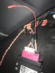
I have a question which is surely stupid
are all ekpm3 compatible with our N54s?
I received an ekpm3 from ebay without worrying about the reference and apparently it comes from an N47
is it good anyway?
ekpm3.jpg